Create

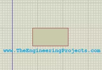
First of all select the 2D Graphics Box Mode as shown in the below figure.

Now click on the workspace and drag the cursor to create a box, as shown in the below figure.
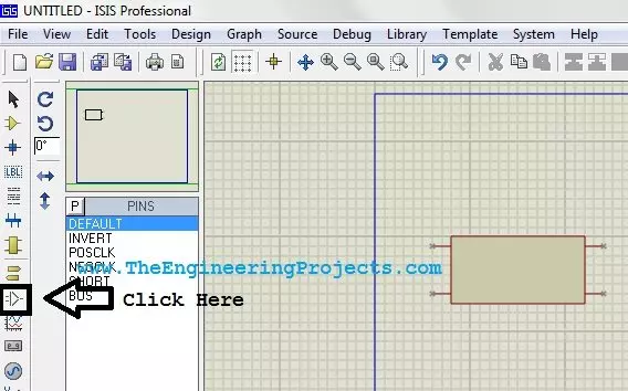
We have created the body of our component, now there’s a need to add pins in it.
For this, click on the Device Pins Mode as shown in the below figure and click on the workspace.
It will add a small pin, attach this pin with the box as I did in the below figure.
Note:
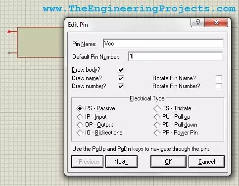
- The pin has a small green bubble on it. Make sure that this end is not connected with the box as this bubble end is for the wire.
- I have added four pins with the box. Now there’s a need to name these pins.
For this purpose, double click any of the attached pin and the properties box will open up as shown in the below figure. - Mention the Pin Name and the Default Pin Number, it will appear on the component and then click on Next.
When you click Next, it will ask for the same things for the second pin and so on.
When you fill these info for all the four pins then click OK.
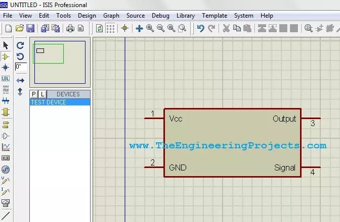
Now when you click the ok button, your component will now look as shown in the below figure.
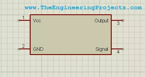
I have given my pins the names as Vcc, GND, Output, Signal.
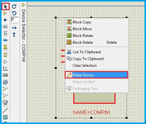
We have completed all the info of our product, now there’s a need to add this component in our library.
For this purpose, select the whole component and then right click and select Make Device.
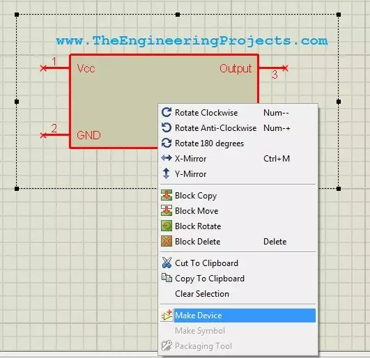
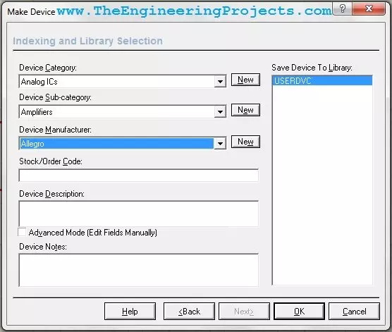
When you click on this option a new dialog box will open up as shown in below figure.
In this dialog box, you just need to give info of your new component so that you can search it easily in your Proteus library.
Just fill the Device Name in it and click Next. I have given the name Test Device to my component.

Now click Next and go on clicking Next, unless you reach at the below page.
Here you need to place your component in the category. Choose the appropriate category for your product and click on OK.
That’s it. Now your component has been added to the library.
Open your part list and search for the component like in my case I search for Test Device and the below component appeared in my list.
Modify
In this article, a user-friendly feature in the Proteus software is presented, which is the Make Device.
For this purpose, 2D Graphics mode of the software is used.
In this article, existing components are selected and their schematic view is modified.
By using the 2D graphics mode, one can design various blocks that are useful for presenting their prototypes.
By using this mode, the colour, shape, size and text related to the component can be modified.
This makes the presentation more attractive and perceivable.
Some of the possible modifications are explained step-by-step in the following examples,
- Modifying the view of a Relay
- Editing an IC or a Microcontroller
- Creating UART Modules by modifying the COMPORT
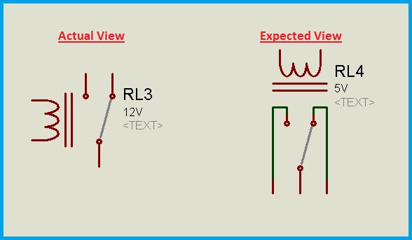
Modifying the view of a Relay
Let’s begin with a simple component, the Relay.
In this example, the shape and the orientation of the component are modified.
A basic relay contains a coil and an SPDT switch. Now, the position of the coil and the switch are modified in this example.
The expected view is shown below and the below procedure explains how to transform from the actual view to the expected view.
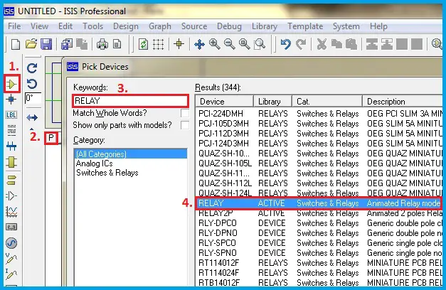
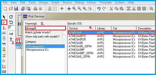
Step1: Select the component from pick devices tab.
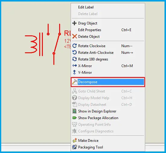
Step2: Place the component on the worksheet. Right-Click the component and then select the ‘Decompose’ option from the Right-Click Menu.
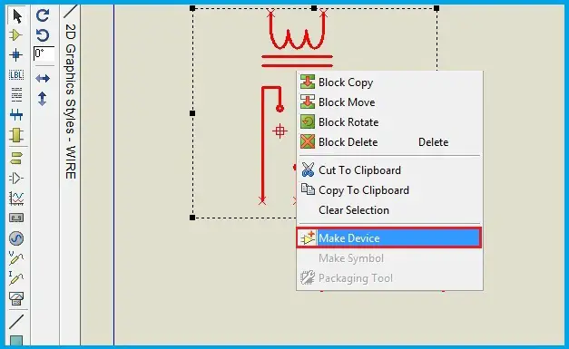
Now, the individual segments or parts of the component get decomposed. So, these parts are now movable or editable.
Select the individual parts and drag them to get the expected view.
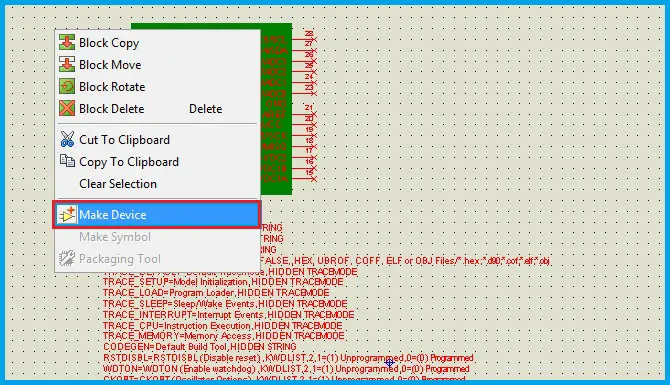
Step3: Select all the parts of the expected view. Right-click the selected part and then select the ‘Make device’ option from the Right-click Menu.
Step4: Through a series of options the name of the component, Index and other reference parameters can be edited or left unchanged.
After this step, the component is created in the library and can be used a regular component by placing it in the workspace.
The decomposed component can be deleted.
Now, let’s verify whether the modified component works similar to the default component or not.
Below is the simulation video that compares the operation of modified and default components.
The procedure to modify the component is also shown.
Editing an IC or a Microcontroller
In the previous example, we have seen the basic modifications like changing the shape through drag and
drop option and changing component properties like the voltage.
Now, let’s go to next level of modification.
In this example, a microcontroller is modified.
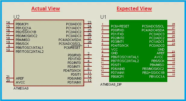
We can convert the existing microcontroller into a development board. The colours, shapes, pins/terminals layout can be changed.
The actual and expected views are shown below.
The component is modified such that it looks like a development board in DIP view.
Step1: Select the component from pick devices tab.
Step2: Place the component on the worksheet. Right-Click the component and then select the ‘Decompose’ option from the Right-Click Menu.
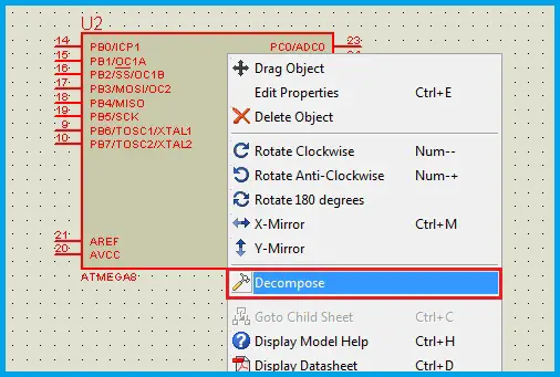 Now, the actual component is split into basic parts. It is the combination of several pins/terminals and a rectangular block.
The component properties are displayed after decomposing the component.
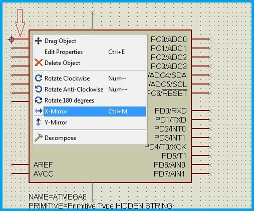
The pin orientation can be modified by mirror option in its Right-Click Menu.
Select the pin to be modified or shifted from one side of the rectangular block to the other side, then Right-Click and select X-Mirror option.
Below is the procedure to ‘mirror’ the pin/part in X-direction.
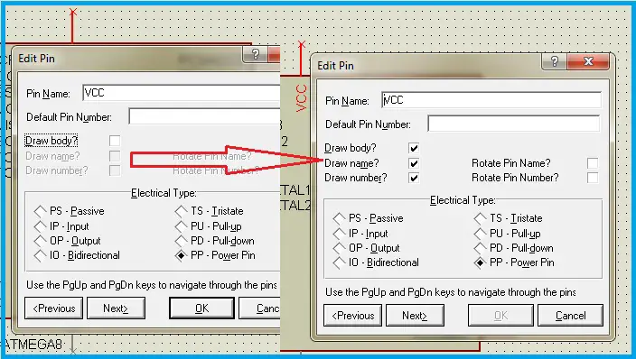
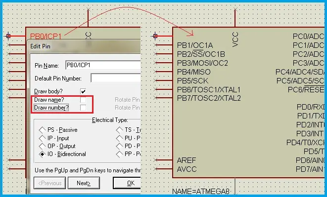
 There are some hidden pins like Vcc and GND. If desired, these pins can be shown along with other components.
Double-Click the hidden pin and edit the properties as desired.
The Pin number, name, their orientations etc.., properties can be modified.
 Now, drag the pins according to the expected view i.e.., the DIP View.
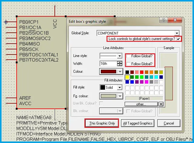
The rectangular block can be resized and the colour of the block also can be changed.
Double-Click on the borderline of the block and a pop window containing properties of the block is displayed.
The border line can be modified in the line attributes like the Line style, Width of the line and the colour of the line can be changed.
The block can be edited in the ‘fill attributes’.
For this purpose the ‘Follow Global’ option need to be Unselected and then editing will be allowed.
 These properties are not only useful while modifying the components but also used to create customized blocks which may or may not be components.
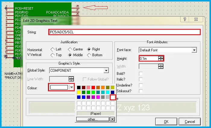
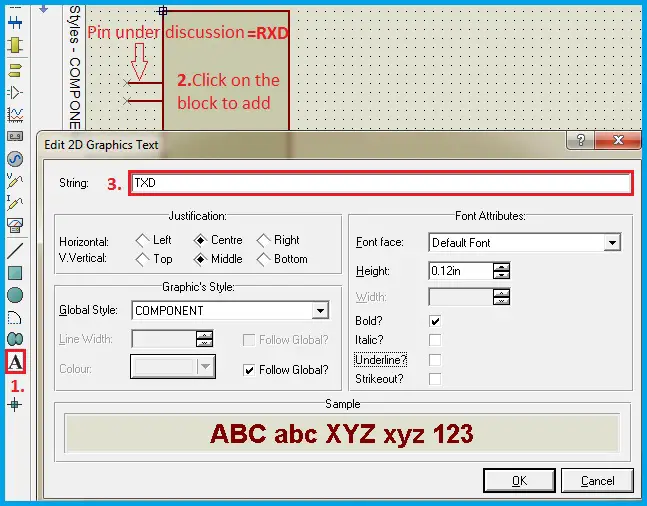
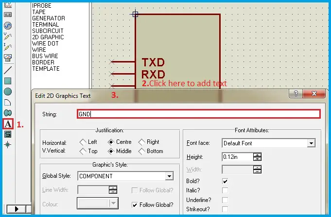
The pin names can be hidden and desired names can be assigned using 2D-Graphics Text mode.
This is useful when we are changing the colour of the block and a contrast colour for the text is required.
The pin names can be hidden from the pin properties as discussed earlier.
The ‘Draw Body’ option of the pin should be selected or otherwise, this pin will be hidden.
 Now, by using 2D-Graphics Text Mode, the pin names can be written in the desired style, colour and font etc..,
Unselect the Follow Global option whenever required.
Similarly, write the Pin numbers as shown below. Make sure that,
the pin numbers a placed at the edge of the pins because during the simulation the State of the pin is graphically indicated beside
the pin name and immediately out of the box.
Step3: Select all the parts of the expected view along with all the component properties. Right-Click the selected part and then select the ‘Make device’ option from the Right-click Menu.
Step4: The name of the component can be changed to a desired one. Do not change the design related files in any of the steps, which may lead to malfunctioning of the component.
Now, let’s verify whether the modified component works similar to the default component or not.
Below is the simulation that video compares the operation of modified and default component.
Same program code is loaded in the microcontrollers which blink the PORTD for every 500mS.
Creating UART Modules-Modifying the COMPORT
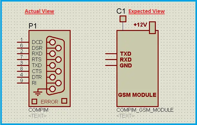
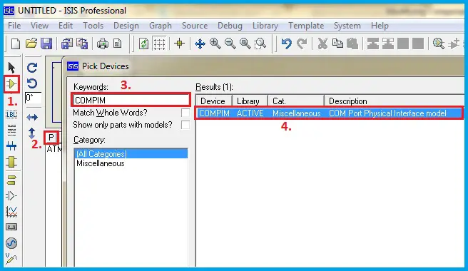
The Proteus software has an option to interface with external modules in real-time through the COMPIM (Comport Physical Interface Module) component.
Its default view is a DB9-Pin Serial Port connector.
This component makes it possible to connect various UART Modules like GSM, GPS, Wi-Fi etc.., in real-time with the circuit designed in the worksheet.
So, to make the circuit more comprehensible, let’s modify the view of this component.
The actual and expected views are shown below,
Step1: Select and place the COMPIM component on the Sheet/Workspace.
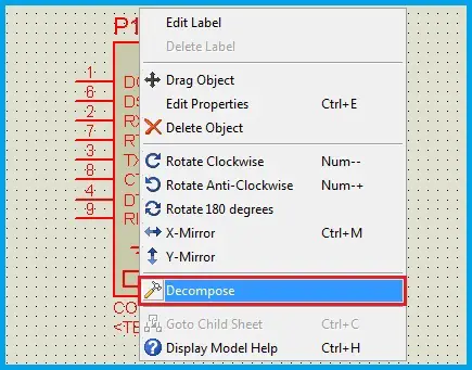
Step2: Right-Click on the component and select ‘Decompose’ from the Right-Click Menu.
 The expected view is similar to the real-time modules like the GSM Module etc..,
which contain TX, RX and GND Pins in common excluding the Power supply terminals.
The expected view is similar to the real-time modules like the GSM Module etc..,
which contain TX, RX and GND Pins in common excluding the Power supply terminals.
As the serial port has Flow control terminals in addition to the previously mentioned pins, we can remove the unwanted pins.
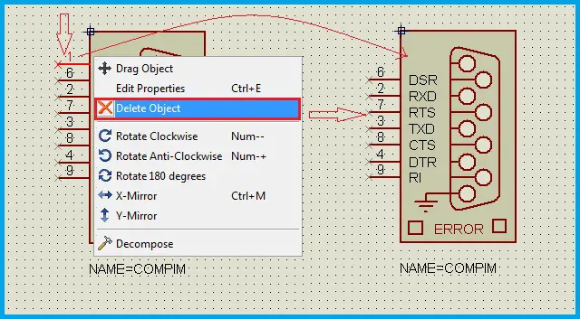 The connector shape can be made invisible either by removing the block or by placing a desired shape over the connector,
but the pins shouldn’t be covered. Every unwanted part like the lines or circles can be deleted.
The connector shape can be made invisible either by removing the block or by placing a desired shape over the connector,
but the pins shouldn’t be covered. Every unwanted part like the lines or circles can be deleted.
‘Any component in the worksheet can be deleted by Double Right-Click on the component or part’.
 The actual circuit connections are such that, the TX, RX pins of the microcontroller are connected to the TX, RX pins of the COMPORT respectively.
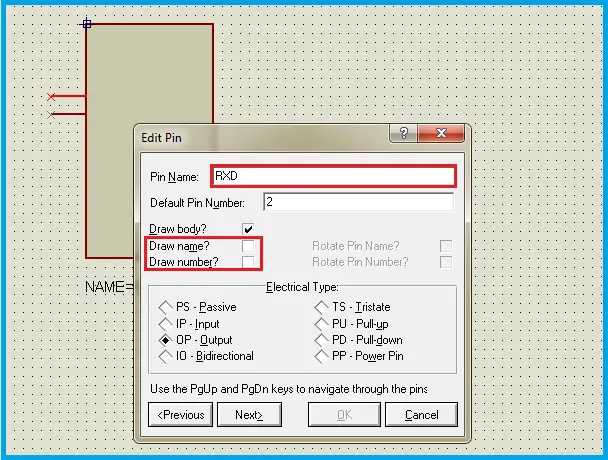
But, the schematic view or in the circuit diagram, the TX and RX pins of the microcontroller and the module are cross-connected.
So, we have to write 2D-Text for the TX and RX pins of the COMPORT as RX and TX respectively.
 The modules have the Ground Pin that should be connected to the circuit ground.
In the software, it is not necessary as they are programmed.
But to show them in the circuit diagram, we can add a new pin for Ground.
The pins mode is used for this purpose.
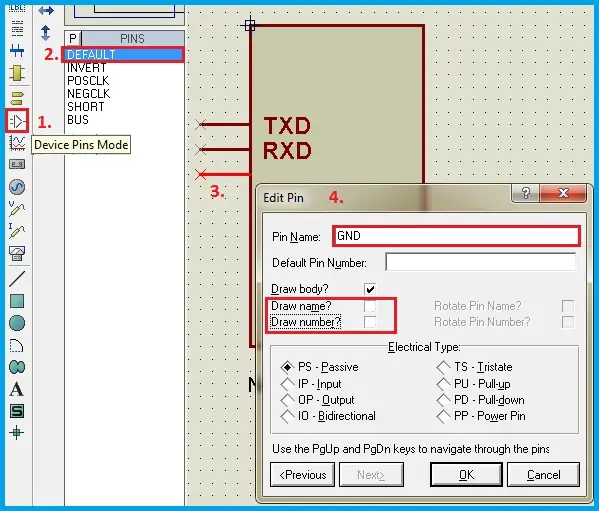 Place the pin on the workspace.
The edge of the pin that has the cross symbol indicates that it should be connected to the external components in the circuit diagram.
Edit the properties of the Pin such that, name and number are hidden.
 Additional text or blocks can be added to enhance the view of the module like the antenna and Power supply block from the 2D-Graphics Box mode.
Step3: Select all the parts of the expected view. Right-click and select ‘Make device’ from the Right-click Menu.
Step4: Through a series of options, the name of the component, Index and other reference parameters can be edited or left unchanged.
After this step, the component is created in the library and can be used a regular component by placing it in the workspace.
The decomposed component can be deleted. Let’s check whether this component is shown in the Devices.
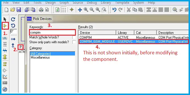 The properties of the component are left unchanged. So, the selection of Port parameters is same as that of the default component.
Let’s connect a module and verify it in real-time. For this purpose, a GSM Module is connected to the computer through a USB-Serial converter.
The port number of this converter is obtained from the ‘Devices and Printers’.
The port parameters in the component are set as shown below.