Blinking LED
- First, use the MPLAB X to generate hex;
- Then, use protelus to draw “Schematic Capture”;

- Finally, import the hex file into the MCU component.
Right-click the "mcu" icon and select "Edit Properties".
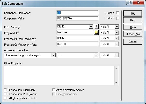
- PIC16F887 or PIC16F877A
- LED
- 470R Resistor
- 8Mhz Crystal
- Two 22pF capacitors in parallel
LIST p=16F887			 ;tell assembler what chip we are using
INCLUDE <P16F887.INC>

 __CONFIG  _CONFIG1, _INTOSCIO & _WDT_OFF & _PWRTE_ON & _MCLRE_ON & _CP_OFF & _CPD_OFF & _BOR_OFF & _IESO_OFF & _FCMEN_OFF & _LVP_OFF & _DEBUG_ON


CBLOCK h'20'
    COUNT1
    COUNT2
ENDC
    ORG		0x00

MAIN:
    BANKSEL		TRISB
    BCF 	    TRISB,0
    BANKSEL		PORTB
MainLoop:
    BCF		    PORTB,0
    CALL		DELAY3
    BSF			PORTB,0
    CALL		DELAY3
    GOTO	    MainLoop            ; Do it again...


DELAY3:
    DECFSZ		COUNT1,1
    GOTO		DELAY3
    DECFSZ		COUNT2,1
    GOTO		DELAY3
    RETURN

END
    title "Blink V. 1.0"
    subtitle "The uC Equivalent of Hello world"

; ***** Program Header *******************************************************************************
    list P=PIC16F18877, ST=OFF, MM=OFF, N=42, B=4, W=1 ; <-- List file directives
    include <p16f18877.inc> ; <--Use the name of your PIC here

; ***** Device Configuration *************************************************************************
    __CONFIG _CONFIG1, _FEXTOSC_OFF & _RSTOSC_HFINT32 & _CLKOUTEN_OFF & _CSWEN_ON & _FCMEN_ON
    __CONFIG _CONFIG2, _MCLRE_ON & _PWRTE_OFF & _LPBOREN_OFF & _BOREN_OFF & _BORV_LO & _ZCD_OFF & _PPS1WAY_OFF & _STVREN_ON
    __CONFIG _CONFIG3, _WDTCPS_WDTCPS_31 & _WDTE_OFF & _WDTCWS_WDTCWS_7 & _WDTCCS_SC
    __CONFIG _CONFIG4, _WRT_OFF & _SCANE_available & _LVP_ON
    __CONFIG _CONFIG5, _CP_OFF & _CPD_OFF

    CBLOCK h'20'
        COUNT1
        COUNT2
    ENDC
    ORG     0x00

MAIN:
    BANKSEL     TRISB
    BCF         TRISB,0
    CALL        Init_Osc
    BANKSEL     PORTB

MainLoop:
    BCF         PORTB,0
    CALL        DELAY3
    BSF         PORTB,0
    CALL        DELAY3
    GOTO        MainLoop            ; Do it again...

; Initialize the PIC Oscillator.
; For the 16F18877,
; page 122 of the data sheet(F version), the OSCCON1 register.
; Set according to Table 6-1(NOSC/COSC Bit Settings) and Table 6-2(NDIV/CDIV Bit Settings):
;  Clock Source: HFINTOSC(110)
;  Clock divider: 8(0011)
; Our byte now looks like this x1100000(0x60) - 32 Mhz.
; Our byte now looks like this x1100001(0x61) - 16 Mhz.
; Our byte now looks like this x1100010(0x62) - 8 Mhz.
; Our byte now looks like this x1100011(0x63) - 4 Mhz.
; Our byte now looks like this x1100100(0x64) - 2 Mhz.
; Our byte now looks like this x1100101(0x65) - 1 Mhz.
; Our byte now looks like this x1100110(0x66) - 500 kHz.
; Our byte now looks like this x1100111(0x67) - 250 kHz.
; Our byte now looks like this x1101001(0x68) - 125 kHz.
Init_Osc:          ; System oscillator set to 4MHz
    banksel OSCCON1
    movlw   0x63
    movwf   OSCCON1
    RETURN

DELAY3:
    DECFSZ      COUNT1,1
    GOTO        DELAY3
    DECFSZ      COUNT2,1
    GOTO        DELAY3
    RETURN

    END